Modbus templates
A Modbus template defines how EnergyGrip communicates with a Modbus device connected to an Aurum gateway, such as a heat interface unit or heat pump. The template describes which registers the device has, how the values in those registers should be read and which registers can be changed from EnergyGrip. Once a template is assigned to a gateway, the device appears on the gateway page and you can read and write its registers.
You can find the Modbus templates under Settings > Modbus templates. This menu item is only visible to users who are allowed to manage templates.
Creating a template
Click the plus sign next to Modbus templates to create a new template. Give the template a recognisable name, for example the brand and type of the device. After saving, the template opens right away so you can add registers.
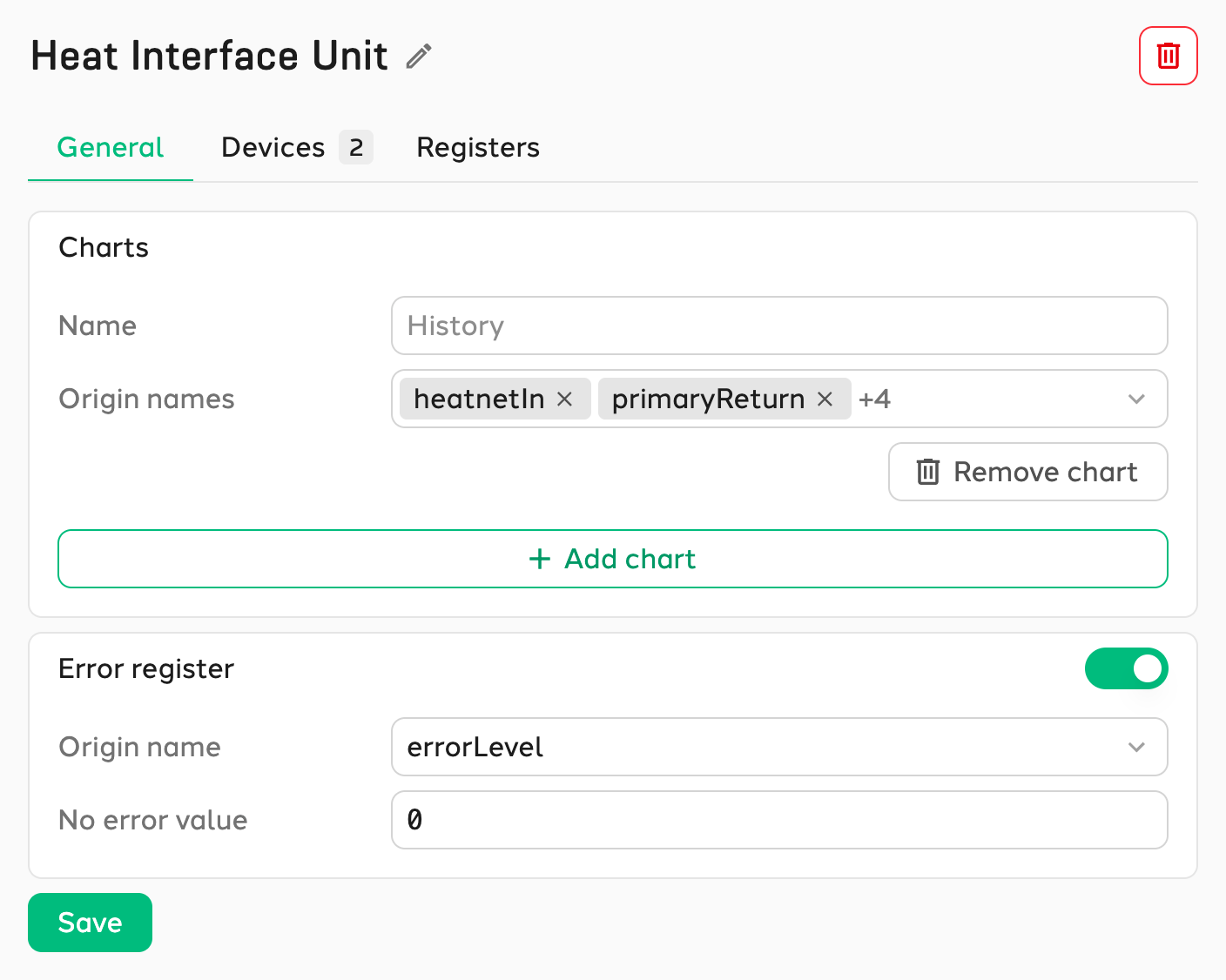
You can rename an existing template with the pencil icon next to the title. The red button in the top right deletes the template.
Added by Aurum
Templates with the Added by Aurum label have been created and tested by Aurum. You can use and edit these templates, but the label may disappear after a change. The template then no longer matches the version that Aurum has verified.
General
The General tab defines what is shown on the overview of the Modbus device.
- Charts: Add one or more charts with the origin names you want to see together in a single chart, for example the supply and return temperatures. A chart without a name gets the title History.
- Error register: Choose the origin name in which the device stores its error code and enter the value the device uses when there is no error (usually
0) under No error value. All other values are shown in the error history of the device.
Devices
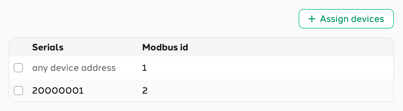
The Devices tab defines which gateways the template applies to. The number next to the tab name shows how many assignments there are.
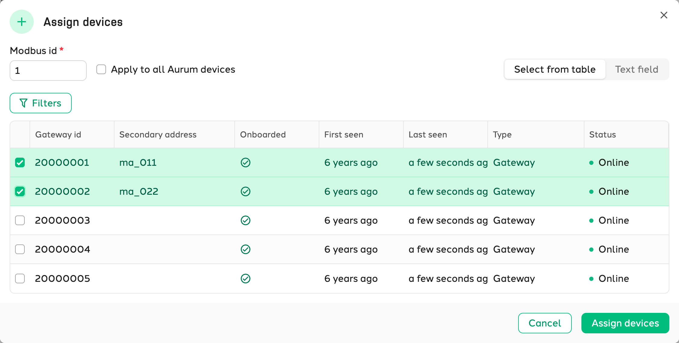
Click Assign devices to create a new assignment:
- Modbus id: The Modbus address of the device on the Modbus bus of the gateway.
- Apply to all Aurum devices: The template is used for every device with this Modbus id, on every gateway within the organisation.
- Select from table or Text field: Uncheck the box to assign the template to specific gateways only. Select the gateways from the table, or paste the serials into the text field (one serial per line, up to 200).
To delete assignments, select them in the table and click Delete assignments.
Registers
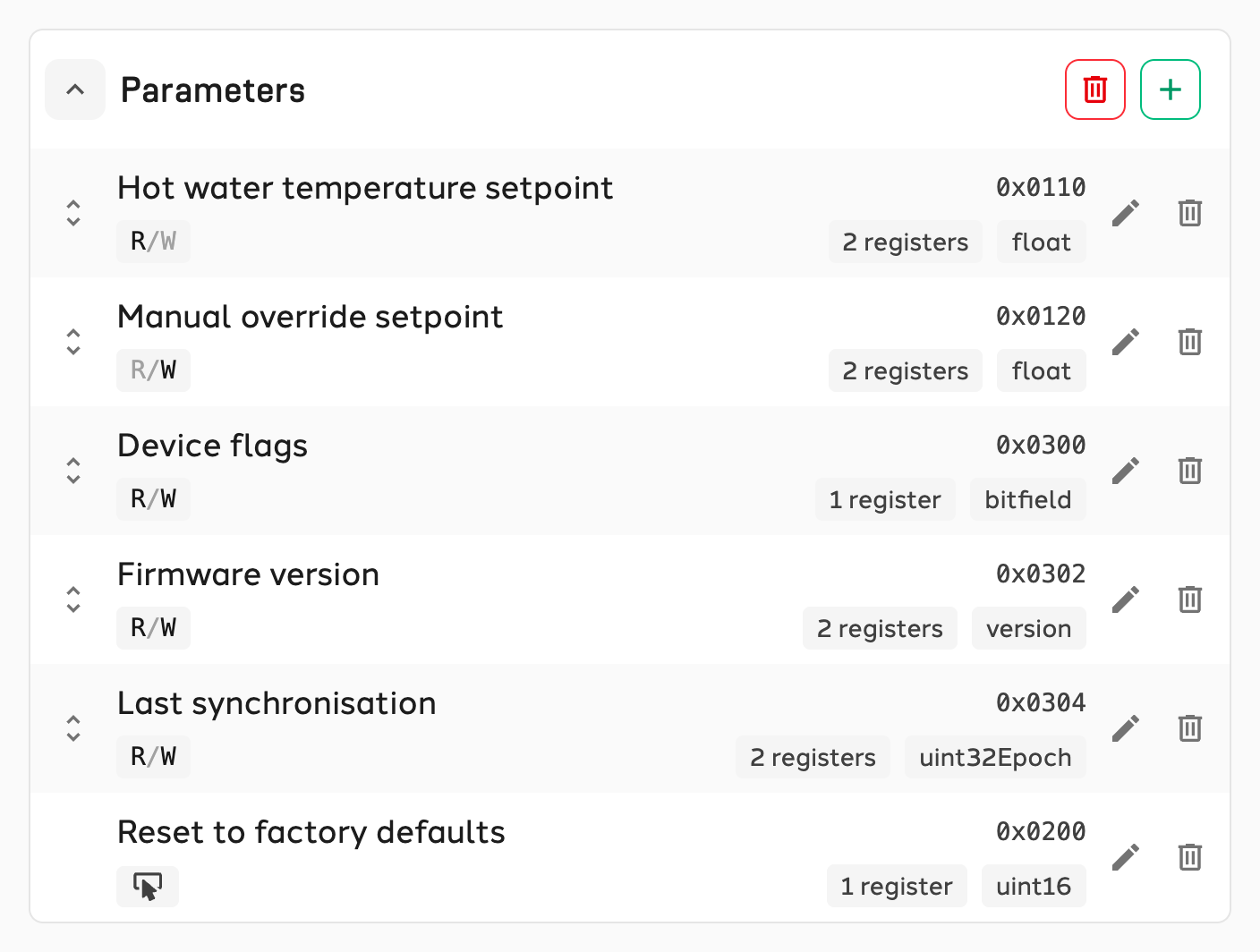
The Registers tab defines which registers the device has. Registers are grouped into categories, such as Operating state or Parameters. Each category appears as a separate section on the device page. You can add a new category at the bottom of the page. Each category can hold up to 25 registers.
Adding a register
Click the plus sign of a category to add a register.
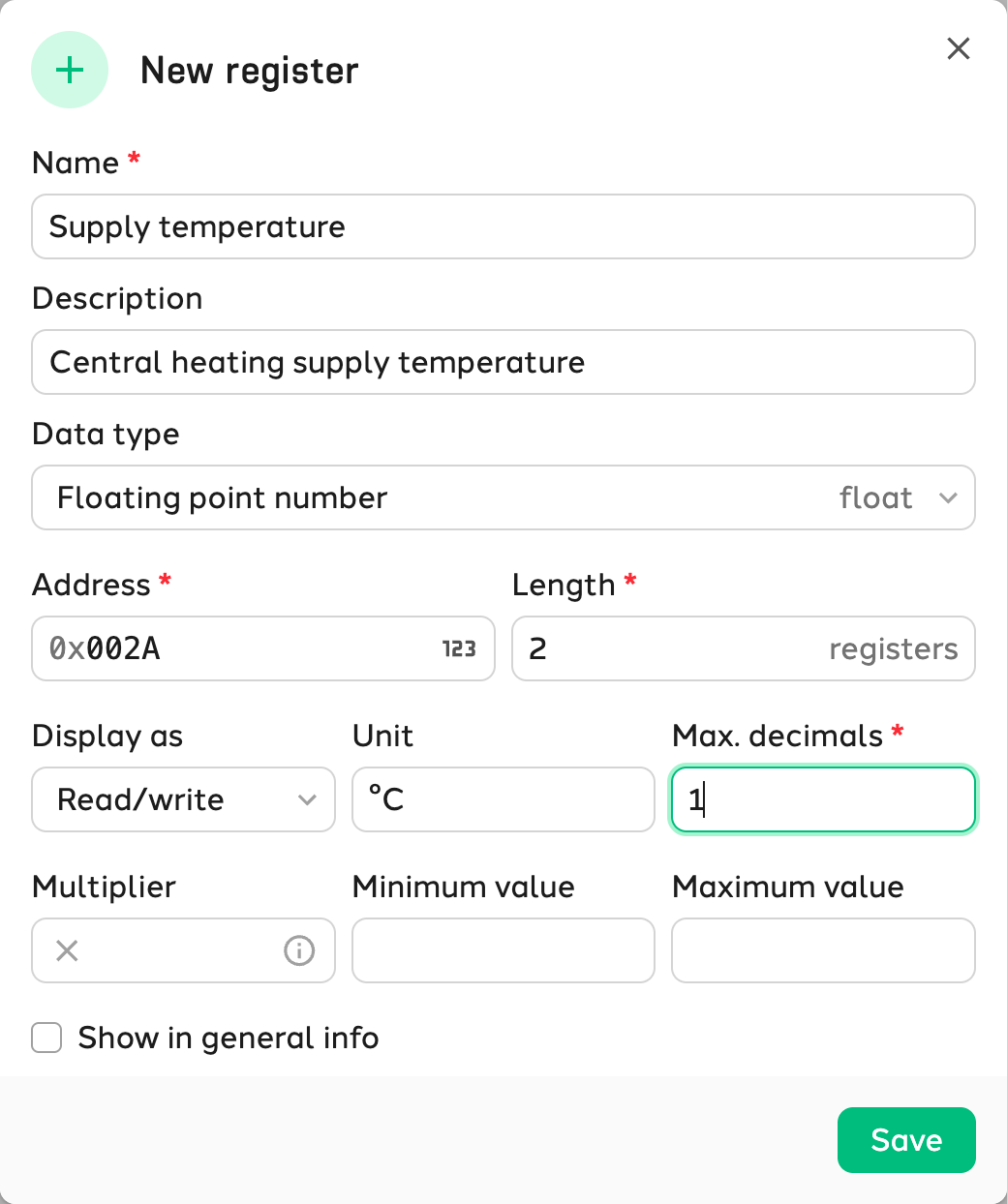
| Field | Explanation |
|---|---|
| Name | The name shown on the device page. |
| Description | Optional explanation of the register. |
| Data type | How the contents of the register are read and written. See Data types. |
| Address | The start address of the register, in hexadecimal notation by default. Use the button in the input field to switch to decimal input. |
| Length | The number of 16-bit (2 byte) registers to read. This is filled in automatically for data types with a fixed length. |
| Display as | How the register is shown on the device page: Read only, Write only, Read/write or Write button. |
| Unit | The unit shown after the value, such as °C or bar. |
| Max. decimals | The maximum number of decimals shown. Only for the float data type. |
| Multiplier | The register value is multiplied by this number when read and divided by it when written. A device that stores 21.5 °C as 215 gets a multiplier of 0.1. |
| Minimum/maximum value | The limits within which a user can enter a new value. Only for numbers that can be written. |
| Value to write | The fixed value written to the register when the write button is pressed, for example to restart the device. |
| Show in general info | Also shows the register in the General info card on the device overview. |
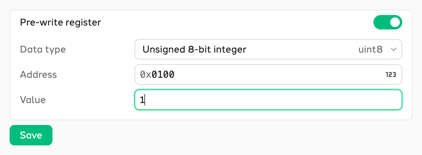
Pre-write register
Some devices only accept a new value after a fixed value has first been written to another register, for example to put the device in configuration mode. In that case, enable the Pre-write register and enter its data type, address and value. EnergyGrip then automatically writes this value before every register you change. Because every change consists of two write actions, a pre-write register lets you save up to 12 registers at once instead of 25.
Data types
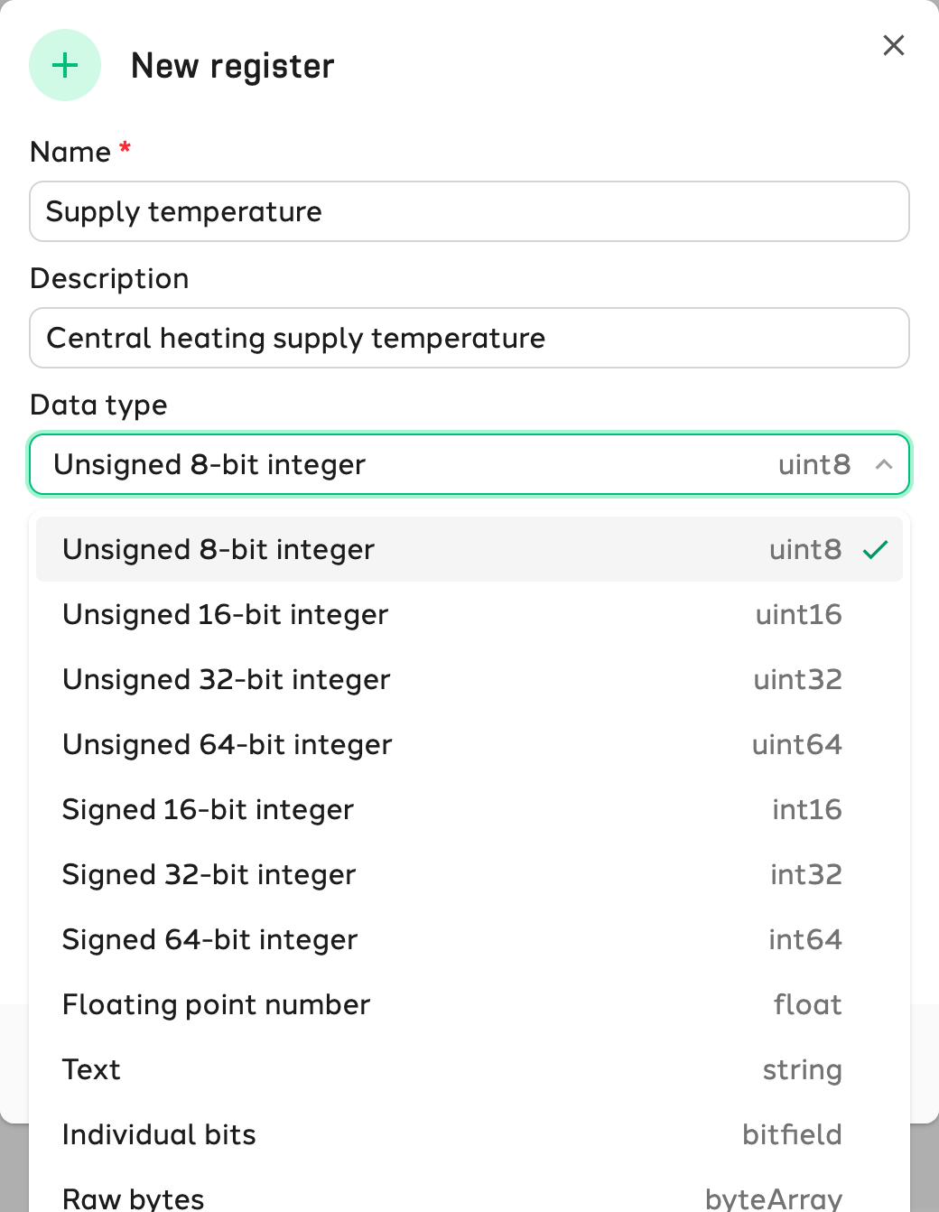
Modbus registers are always 16 bits (2 bytes) in size. Values that need more space span multiple consecutive registers. EnergyGrip reads these registers in big-endian order: the first register and the first byte contain the most significant part of the value.
Numbers
| Data type | Description | Registers | Range |
|---|---|---|---|
uint8 | Unsigned 8-bit integer | 1 | 0 to 255, only the least significant (right) byte of the register |
uint16 | Unsigned 16-bit integer | 1 | 0 to 65,535 |
uint32 | Unsigned 32-bit integer | 2 | 0 to 4,294,967,295 |
uint64 | Unsigned 64-bit integer | 4 | 0 to 18,446,744,073,709,551,615 |
int16 | Signed 16-bit integer | 1 | −32,768 to 32,767 |
int32 | Signed 32-bit integer | 2 | −2,147,483,648 to 2,147,483,647 |
int64 | Signed 64-bit integer | 4 | −9,223,372,036,854,775,808 to 9,223,372,036,854,775,807 |
float | Floating point number | 2 | 32-bit floating point number (single precision) |
A multiplier and a minimum and maximum value are only available for these number types.
Other data types
| Data type | Registers | Input and display | Example | Explanation |
|---|---|---|---|---|
string | Free, 2 characters per register | Text | HIU-200 | Two characters per register, so a text of 16 characters needs 8 registers. |
bitfield | Free, 16 bits per register | Sequence of 0s and 1s | 10110011 | Each bit is a separate on/off status. The rightmost bit is bit 0. |
byteArray | Free, 2 bytes per register | Hexadecimal (0x…) or comma-separated decimal bytes | 0xFF01A2 or 255, 1, 162 | Raw bytes, for example calibration data. Each decimal number is one byte (0 to 255). |
version | 1 or 2 | Version number with 2 or 3 parts | 1.2 or 1.2.4 | One byte per part, so up to 255 per part. 1 register allows 2 parts, 2 registers allow 3. |
uint32Epoch | 2 | Date and time | 01-01-2026 13:00 | Seconds since 1 January 1970 (UTC), shown in your own time zone. Works until 7 February 2106. |
uint64EpochSec | 4 | Date and time | 01-01-2100 00:00 | Like uint32Epoch, but in 64 bits and without a practical upper limit. |
Viewing a Modbus device
Once a template is assigned to a gateway, the Modbus device appears as a tile on the gateway page and on the location page. Click the tile to open the device page.
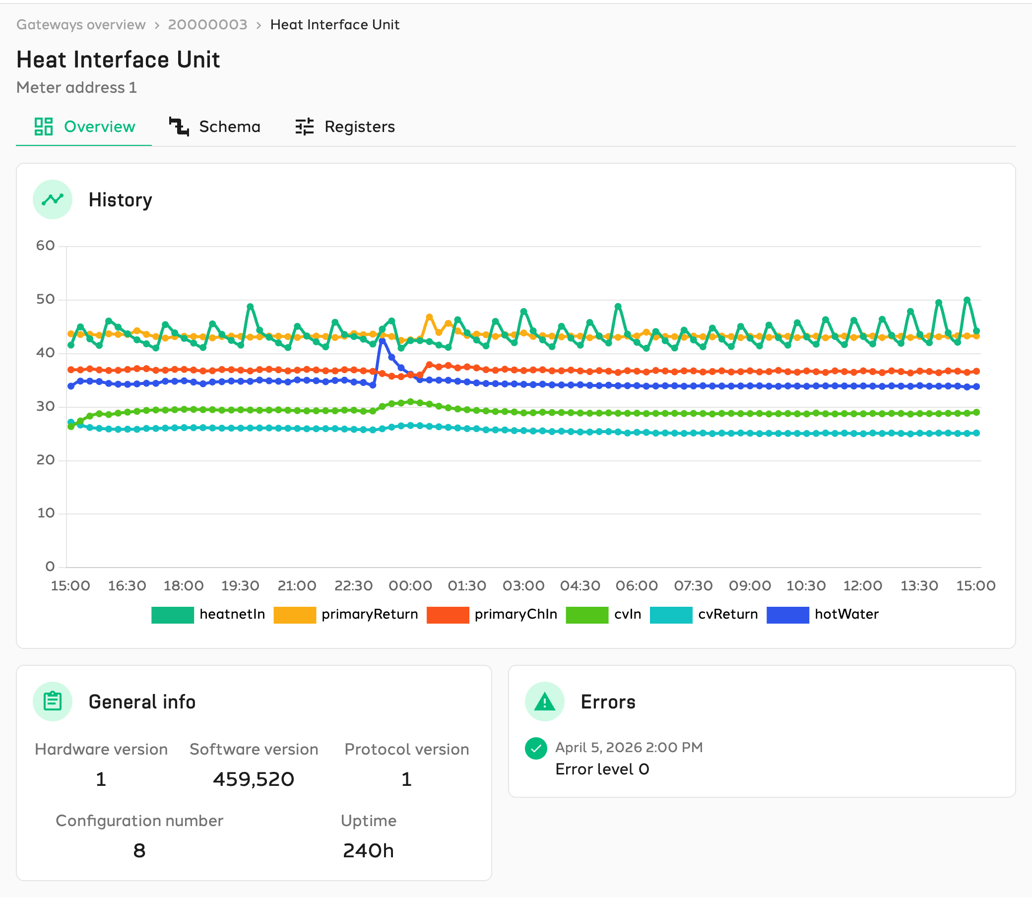
The Overview shows the general info, the charts and the error history of the past 28 days, as configured on the General tab of the template.
The Registers tab shows the current values of the device per category. Fields that can be written can be changed directly. Then click Save to send the new values to the device, or Reset to undo the changes. You can save up to 25 registers at once. Registers with a write button are executed directly with Execute.
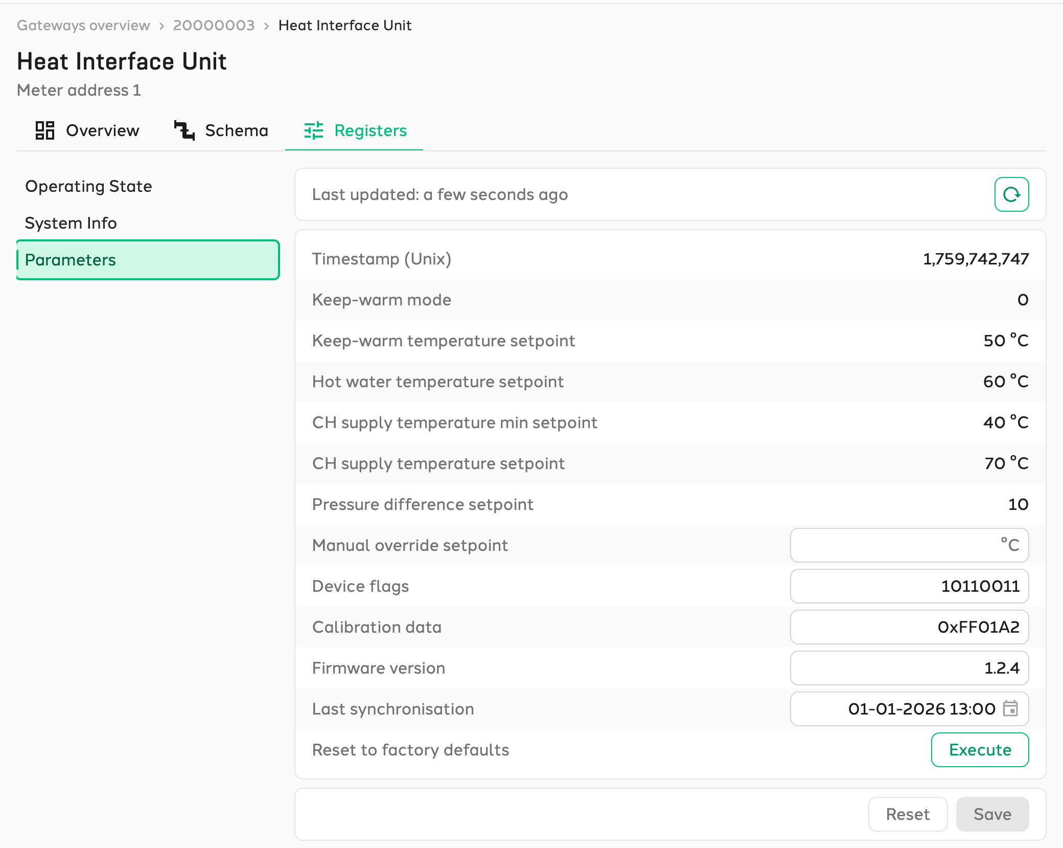
If the device cannot be reached, a message is shown. In that case, check whether the gateway is online and whether the device is correctly connected on the configured Modbus id.